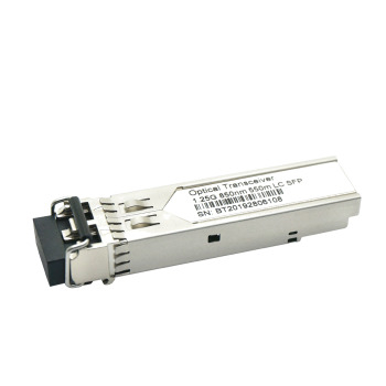
FTTX 1.25Gbps/1.0625Gbps and 20km transmission distance with OC24-01/OC24-01I fiber optic SMF module

5 Pieces
MOQ
$9.00(5 - 49 Pieces) $7.80(50 - 99 Pieces) $6.50(>=100 Pieces)
Price
FTTX 1.25Gbps/1.0625Gbps and 20km transmission distance with OC24-01/OC24-01I fiber optic SMF module
Features Gallery Product Description Request A Quote
Features
Specifications
Model Number: OC24-01/OC24-01I
Type: Optical Fiber Module
Use: FTTX
Warranty Time: 1year
Fiber Type: Fiber Multimode
Wavelength: 850nm
Distance: 550m
Certification: CE FCC ROHS
Power Input: 3.3V
Data Rate: 1.25Gbps
Connector Type: SFP
Compatibility: All Brands
SFP Connector: DDM
Selling Units: Single Item
Basic Infomation
Certification: CE FCC ROHS
Model Number: OC24-01/OC24-01I
Payment & Shipping Terms
Packaging Details: According to quantity ,we can provide professional package, 10/20/36 pcs in one anti-static plastic box, retail package. We can also do as your requirement.
Product Description
Product Description
The SFP transceivers are high performance, cost effective modules supporting dual data-rate of 1.25Gbps/1.0625Gbps and 550m transmission distance with MMF.
The transceiver consists of three sections: a VCSEL laser transmitter, a PIN photodiode integrated with a trans-impedance pre-amplifier (TIA) and MCU control unit. All modules satisfy class I laser safety requirements.
The transceivers are compatible with SFP Multi-Source Agreement (MSA) and SFF-8472. For further information, please refer to SFP MSA.
Features
1. Data-rate of 1.25Gbps operation
2. 850nm VCSELlaser and PIN photodetector
3. Compliant with SFP MSA and SFF-8472 with duplex LC receptacle
4. Digital Diagnostic Monitoring: Internal Calibration or External Calibration
5. 500mtransmissionwith 50/125µm MMF
6. 300m transmissionwith 62.5/125µm MMF
7. Compatible withRoHS
8. +3.3V single power supply
9. Operating case temperature:t
Standard : 0 to +70°C
Extended : -40 to +85°C
Absolute Maximum Ratings
Parameter
Symbol
Min
Max
Unit
Supply Voltage
Vcc
-0.5
4.5
V
Storage Temperature
Ts
-40
+85
°C
Operating Humidity
-
5
85
%
Recommended Operating Conditions
Parameter
Symbol
Min
Typical
Max
Unit

Operating Case Temperature
Standard
Tc
0

+70
°C
Extended
-20

+85
°C
Power Supply Voltage
Vcc
3.13
3.3
3.47
V
Power Supply Current
Icc


300
mA
Data Rate

1.25

Gbps
Optical and Electrical Characteristics
Parameter
Symbol
Min
Typical
Max
Unit
Notes
Transmitter
Centre Wavelength
λc
830
850
860
nm

Spectral Width (RMS)
∆λ


0.85
nm

Average Output Power
Pout
-9.5

-3
dBm
1
Extinction Ratio
ER
9


dB

Optical Rise/Fall Time (20%~80%)
tr/tf


0.26
ns

Data Input Swing Differential
VIN
400

1800
mV
2
Input Differential Impedance
ZIN
90
100
110
Ω


TX Disable
Disable

2.0

Vcc
V

Enable

0

0.8
V


TX Fault
Fault

2.0

Vcc
V

Normal

0

0.8
V

Receiver
Centre Wavelength
λc
770

860
nm

Receiver Sensitivity


-18
dBm
3
Receiver Overload

-3


dBm
3
LOS De-Assert
LOSD


-20
dBm

LOS Assert
LOSA
-30


dBm

LOS Hysteresis

1

4
dB

Data Output Swing Differential
Vout
400

1800
mV
4

LOS
High
2.0

Vcc
V

Low


0.8
V

1. The optical power is launched into MMF.
2. PECL input, internally AC-coupled and terminated.
3. Measured with a PRBS 27-1 test pattern @1250Mbps, BER ≤1×10-12.
4. Internally AC-coupled.
Timing and Electrical
Parameter
Symbol
Min
Typical
Max
Unit
Tx Disable Negate Time
t_on


1
ms
Tx Disable Assert Time
t_off


10
µs
Time To Initialize, including Reset of Tx Fault
t_init


300
ms
Tx Fault Assert Time
t_fault


100
µs
Tx Disable To Reset
t_reset
10


µs
LOS Assert Time
t_loss_on


100
µs
LOS De-assert Time
t_loss_off


100
µs
Serial ID Clock Rate
f_serial_clock


400
KHz
MOD_DEF (0:2)-High
VH
2

Vcc
V
MOD_DEF (0:2)-Low
VL


0.8
V
Diagnostics Specification
Parameter
Range
Unit
Accuracy
Calibration

Temperature
0 to +70

°C

±3°C

Internal / External
-20 to +85
±3%
Voltage
3.0 to 3.6
±3%V
±3°C
Internal / External
Bias Current
0 to 100
mA
±10%
Internal / External
TX Power
-9.5 to -3
dBm
±3dB
Internal / External
RX Power
-22 to -3
dBm
±3dB
Internal / External
Pin Descriptions
Pin
Signal Name
Description
Plug Seq.
Notes
1
VEET
Transmitter Ground
1

2
TX FAULT
Transmitter Fault Indication
3
Note 1
3
TX DISABLE
Transmitter Disable
3
Note 2
4
MOD_DEF(2)
SDA Serial Data Signal
3
Note 3
5
MOD_DEF(1)
SCL Serial Clock Signal
3
Note 3
6
MOD_DEF(0)
TTL Low
3
Note 3
7
Rate Select
Not Connected
3

8
LOS
Loss of Signal
3
Note 4
9
VEER
Receiver ground
1

10
VEER
Receiver ground
1

11
VEER
Receiver ground
1

12
RD-
Inv. Received Data Out
3
Note 5
13
RD+
Received Data Out
3
Note 5
14
VEER
Receiver ground
1

15
VCCR
Receiver Power Supply
2

16
VCCT
Transmitter Power Supply
2

17
VEET
Transmitter Ground
1

18
TD+
Transmit Data In
3
Note 6
19
TD-
Inv. Transmit Data In
3
Note 6
20
VEET
Transmitter Ground
1

<IMG src="//u.alicdn.com/js/5v/esite/img/img-placeholder.png" data-src="//sc04.alicdn.com/kf/Hef2db66bcb7447d89af7eda7e7d8978c7/2518
Recommended Products
Get in touch with us
Characters Remaining(20/3000)